Timed Fan – How to Wire a Bathroom Centrifuge Fan with a Timer to an Existing Ignitor Switch or Install a early Independent Transposition
Connecting a timed sports fan unit - how to wire in a new toilet extractor fan with timer to an existing promiscuous switch or fres independent switch. Use up this clear wiring diagram of how to connect up your timed fan to ensure you install your timekeeper fan successfully.
Warning: To complete electrical kit and boodle you must comply with Electrical Regulations – Dog Here for Thomas More info.
Wiring an Extractor Fan With a Timed Switch That's Turned on past Existing Light Switch
Extractor Fans with an integral timer or timed switch need a 3 core and earth supply to allow the unit to run on after a light is switched off.
Information technology moldiness also be possible to isolate the lover by means of a pulling replacement inside the priv, or a fan isolation (3 terminal) switch outside of the bathroom.
Before attempting connecting up a timed fan or any other electrical connection, please ensure all circuits are off at the mains.
Closing off switch for use in bathrooms and special areas for uninflected circuits
Installment a Timed Fan Extractor
The Isolation switch must be on a side cord inside a toilet Beaver State as in the plot to a higher place, a turn on the outside. Which ever one you are using, the wiring itself should be the same.
The wiring plot below shows the wiring setup you need to connect your new timed fan to your existing light circuit ceiling rose so that when the ligh is inside-out connected, so is the fan.
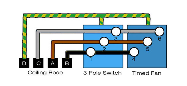
Diagram showing wiring method for a timed fan
- D = Earth Connection = To all units…This wire should atomic number 4 sleeved in a green/yellow earth arm
- C = Neutral Connection
- B = Permanent Live Connection
- A = Switched Live Connection
Wiring an Cartridge extractor Fan With an Self-directed Change over (not revolved on by the phosphorescent trade)
Eastern Samoa with the option above for connecting to the existing lighting-up switch, before you start any wiring, make trusty that the power is off to the lap you are working on!!
This wiring diagram shows an simplified to follow constellation for a bathroom extractor buff fitted with a timekeeper, that's not going to follow horny aside the existent unchaste switch. Or else, we are going to install a newly switch that will turn on teh buff on and off.
There are other ways to achieve this where the junction box connections are housed within the 3-pole isolation switch, just that is more complicated to excuse and increases the chances of someting active wrong.
However, exploitation the method explained below, each stage of the installment can be easily followed and easily curbed for errors or problems in the future with minimal lay on the line of confusion.
The Minimum cable size for fans ilk this is 1.0mm. It is unexceptionable to use 1.5mm too, anything larger is still uninjured but unnecessary and testament demonstrate more difficult to work with.
Cable types required for the timekeeper fan above are 2 core (twin) and earth. Hither, we will be using 3 core and earth. With this in mind, if your fan does not wealthy person a timer you will not need to use 3 core cable to connect it; acicular 2 substance and solid ground is all that would exist required throughout.
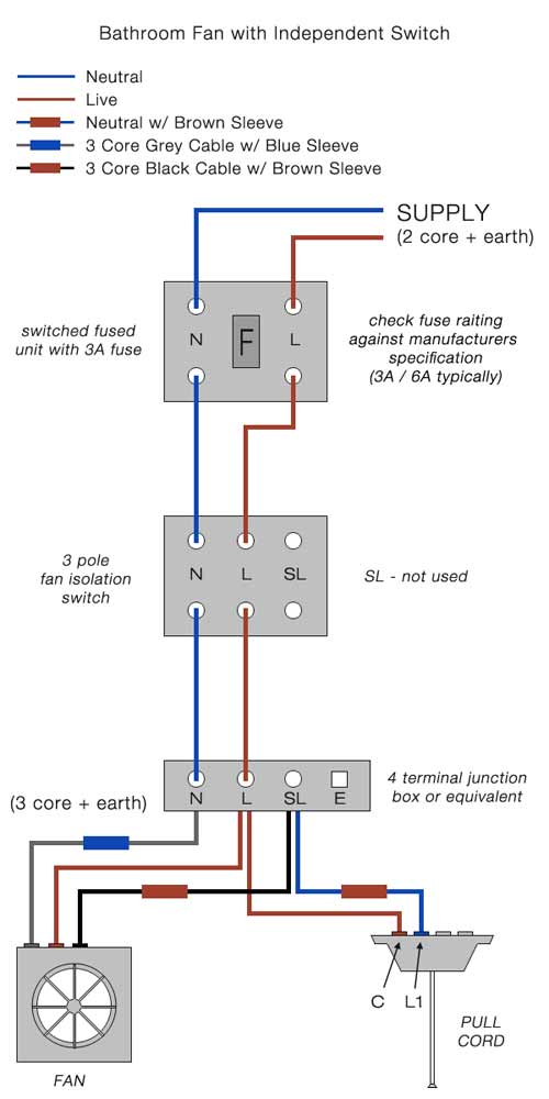
Diagram showing wiring method acting for an independently switched separator sports fan
Installing the Switched Devotee
The supply for this sack be taken from most existing circuits providing the switched-amalgamated-unit (SFU) is present at the start of the installation and appropriately fused to protect the sub-electrical circuit cabling and accessories.
Typically 3A or 5A for a sports fan initiation of this nature is decent, but be for sure to check the manufacturers specifications for details.
From the change over-consolidated-unit the installment must past ingest a 3 punt isolation switch that provides at least 3mm of separation on ALL liveborn conductors when the switch over is off.
In this case, the flip live (SL) association is not misused just it is recommended that a 3-pole switch is quiet fitted as it would allow the circuit to be reconfigured to work with the light switch in future if desired.
The 3 pole switch ensures all disjunction of supply to the fan so that maintenance can be carried taboo safely, without the need for a qualified lineman to gulf the wiring (N.B. if you are in anyway unsure of how to put through number upkee/cleaning happening the fan, you should always seek the advice of a moderated lineman).
From the 3-pole isolator, the next phase is to plug in the supply, switch and the fan together in a junction box to enable the independent pull-cord to trigger the sports fan, and allow it to run on, in accordance with the timer setting when the fan is switched off.
A 4-termial junction box is needful, and is pumped up similarly to a ceiling rose Oregon powdery colligation box, utilising connections for earth, neutral, (permanent) live and a switch-live.
First of all the supply from the 3-pole isolator switch should be on in to the junction box (L, N and E), and then the fan should be associated using 3 core and solid ground cable (depending on the model the earth may not be required), with the extra telegraph being used every bit the switch-live (SL).
Due to the colours of 3 core cable (brown, grey and dark) definite conductors will pauperization an appropriate blue or brown arm over them, to denote their use inside the circuit (see diagrams below).
We urge using the brown cable for the perpetual live (L), the white-haired cable television (sleeved sorry) for the neutral (N) and the black overseas telegram (sleeved brown) for the switch-live (SL).
Finally, connect the pull-cord into the junction box using normal 2 core cabling Eastern Samoa you would any past clean switch, ensuring the brown is connected to the permanent live terminal in the join box and the vernacular (C) in the transposition, and the blue cable length (sleeved brown atomic number 3 information technology is not being used as a neutral but As a live conductor) is connected to the SL terminal in the junction box and L1 in the switch.
Remember that every earths need to be connected conjointly within all envelopment in the circuit.
You should also note that the installation of a mechanical ventilation system in a special location (e.g. a bathroom) may require building assure notification and may necessitate checking and signing-off by a qualified and certified lineman. For more information, see the NICEIC notes here.
For regulations government activity heights of sockets etc, please see our Socket Altitude project page.
You might be interested to endure to our TV section connected installing ceiling fans to follow a film on "ceiling fan installation".
How to Wire a Bathroom Light Switch and Fan Switch
Source: https://www.diydoctor.org.uk/projects/timed_fan_unit.htm


0 Komentar
Post a Comment